- FMA
- The Fabricator
- FABTECH
- Canadian Metalworking
Categories
- Additive Manufacturing
- Aluminum Welding
- Arc Welding
- Assembly and Joining
- Automation and Robotics
- Bending and Forming
- Consumables
- Cutting and Weld Prep
- Electric Vehicles
- En Español
- Finishing
- Hydroforming
- Laser Cutting
- Laser Welding
- Machining
- Manufacturing Software
- Materials Handling
- Metals/Materials
- Oxyfuel Cutting
- Plasma Cutting
- Power Tools
- Punching and Other Holemaking
- Roll Forming
- Safety
- Sawing
- Shearing
- Shop Management
- Testing and Measuring
- Tube and Pipe Fabrication
- Tube and Pipe Production
- Waterjet Cutting
Industry Directory
Webcasts
Podcasts
FAB 40
Advertise
Subscribe
Account Login
Search
How to set a press brake backgauge manually
Reader questions on press brake setup and material springback
- By Steve Benson
- April 18, 2024
Question: I have a press brake with no backgauge fingers, which means everything in the shop must be hand-marked on the flat before we bend it. Is there a way we can calculate exactly where the bend line should be? The machine we have does not require line-of-sight calculations, as the top tooling can be easily seen all the way down until it impacts the metal. We primarily dimension our flashings using the outside sizes. It has been a bit of a headache for all of us trying to mark out accurate bend lines without making lots and lots of mock runs and, hence, wasting loads of material.
Answer: Yes, and here’s how it’s done. Mount and seat your punch and dies into the press brake and then center them. The best way to ensure the punch is centered into the die space is to bring the punch into gentle contact with the die faces and then stroke the ram. By this I mean you need to repeatedly cycle the ram and run the punch into the die space. While doing this, get to a position where you can see down the length of the tools.
See if the die moves. If it does, adjust the bed to the right or left until you see no die movement. Remember that the nose of the punch establishes the bend line, the center of the bend. You will see in a moment why the centering of the punch and die is so essential.
Next—and this is important—go to the other end of the press brake and again check for movement. If you see none, then you are good to go. However, if you need to adjust the tools to correct the centering, then you must (and I stress must) go back to the other side of the brake and recheck the centering. If you adjust one side, you will affect the other side.
You may need to check and recheck the die several times before all die movement has ceased. Trust me on this one. It is worth the time and energy in the long run.
Now that the punch is firmly seated and centered, you can locate the bend line. There are two ways to accomplish this, depending on whether you are using a bend deduction (BD) or bend allowance (BA) for your layouts.
If you’re using the BA to calculate the flat pattern, you will need to take the dimension from the sheet edge (or the previous bend) to the tangent point between the leg (the flat) and the outside radius. To that, you add half of the calculated BA that was used to develop the flat pattern (see Figure 1). If you’re using the BD, take the outside dimension of the flange to be formed and subtract half the BD.
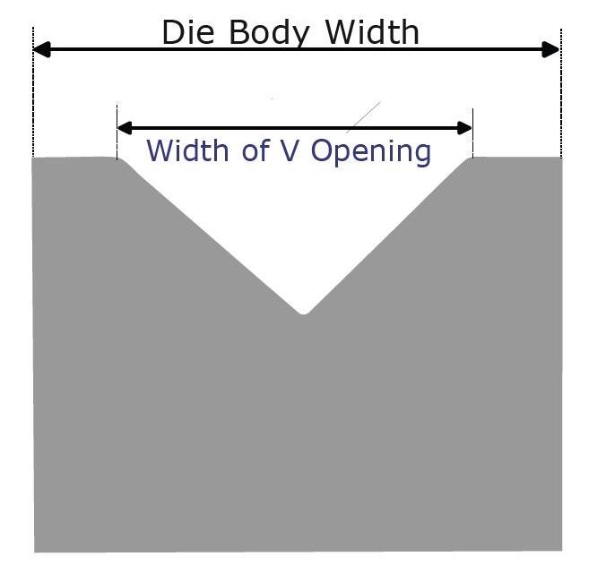
Next, measure the width of the die body. I am not talking about the width of the V here, but rather the outside faces of the die (see Figure 2). Please note that the V might not be centered in the die. This is especially common with planer or modified tooling. If it isn’t centered, note the dimension from the center of the V and the front face of the die—you’ll need this in a minute.
Get your adjustable square ruler with an appropriate length of precision blade. How much blade is appropriate? Let’s add it up. Add the edge-to-bend line dimension you calculated earlier to one-half the die body width or, if the V isn’t centered in the die body, from the front face of the die to the center of the V. Then, set your square blade to measure that dimension as closely as possible. If you are working with imperial (SAE) measurements, a 16R scale works best. If you are working in metric, 11MH scale is appropriate.
Now, you have what you need to set the backgauge position. For safety reasons, raise and block the ram. Then, place the square head against the front face of the die with the blade over the top of the die. You will most likely need someone else to hold the head against the die while you go around to the back of the press brake (see Figure 3).
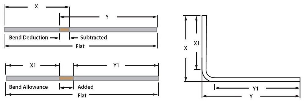
FIGURE 1. This shows how to develop your flat using the bend allowance (BA) or bend deduction (BD). To calculate where to set your backgauge manually for flange Y, you add half the die body width (or dimension of the V center to the die front face) to your previously calculated flange dimension, either Y1 + 1/2BA or Y - 1/2BD.
Firmly mount a crossbar to the angle iron supports and then clamp a stop using a single clamp in one place. Next, slowly pivot the stop until it touches the square and set a second clamp to hold the stop in position (see Figure 4). Now, repeat the process for the second stop.
You can see how important it is to center the punch and die and ensure that the backgauges are in the correct location. As it is, even under perfect conditions—and depending on the tolerances you are working with—it will still take several setup parts to get it right. Nonetheless, you will now form more accurately than you could by just using a scribe and eyeballing it.
How to Dial In Your Springback Estimates
Question: We’re forming a variety of high-carbon spring steels and stainless steels, and we’re hoping to better predict springback. In your previous columns on thefabricator.com, including “The hows and whys of springback and springforward,” you’ve referred to the springback factor, which is the outside bending angle (before the material is released from pressure) divided by the outside bent angle after springback. You also mention a material factor. Can we find the material factor anywhere for specific material grades? We’re using 1070/1080 material as well as stainless steel 301. Some of our material is annealed and some grades are hardened and tempered.
Answer: I do not know any specific place to locate the type of material factor data you’re looking for. Most of that information is found on a case-by-case basis. In other words, you’ll need to do some in-house testing, charting, and analysis specific to a particular material and process. This will be the most accurate way to determine your material factor, simply because of the wide tolerances applied to every aspect of any metal, such as thickness, hardness, tensile strength, and yield strength.
In the article you cite, I write about a baseline material factor of 1.0 for cold-rolled steel, and I do give material factors for H32 aluminum and 304 stainless steel—but again, these just give you a starting point. The reality is that no two pieces of material are the same. They are usually not wildly different, but different enough that the material factor you use will not always provide a perfect answer. It is only a rule-of-thumb value. Nonetheless, after some in-house research and testing, you will find that your springback estimates will get pretty close.
subscribe now

The Fabricator is North America's leading magazine for the metal forming and fabricating industry. The magazine delivers the news, technical articles, and case histories that enable fabricators to do their jobs more efficiently. The Fabricator has served the industry since 1970.
start your free subscriptionAbout the Author

Steve Benson
2952 Doaks Ferry Road N.W.
Salem, OR 97301-4468
503-399-7514
Related Companies
- Stay connected from anywhere

Easily access valuable industry resources now with full access to the digital edition of The Fabricator.

Easily access valuable industry resources now with full access to the digital edition of The Welder.

Easily access valuable industry resources now with full access to the digital edition of The Tube and Pipe Journal.
- Podcasting
- Podcast:
- The Fabricator Podcast
- Published:
- 04/30/2024
- Running Time:
- 53:00
Seth Feldman of Iowa-based Wertzbaugher Services joins The Fabricator Podcast to offer his take as a Gen Zer...
- Industry Events
Pipe and Tube Conference
- May 21 - 22, 2024
- Omaha, NE
World-Class Roll Forming Workshop
- June 5 - 6, 2024
- Louisville, KY
Advanced Laser Application Workshop
- June 25 - 27, 2024
- Novi, MI
Precision Press Brake Certificate Course
- July 31 - August 1, 2024
- Elgin,


